MappyDot Plus Calibration
The VL53L1X has 3 different calibration modes which implement the standard VL53L1X API calibration routines. More information about these calibration functions can be found in the ST VL53L1X API documentation.
- Reference SPADs calibration - Calibrates the SPAD arrays.
- Offset calibration - Calibrates the offset of the sensor. This should be performed after assembly (including a glass cover).
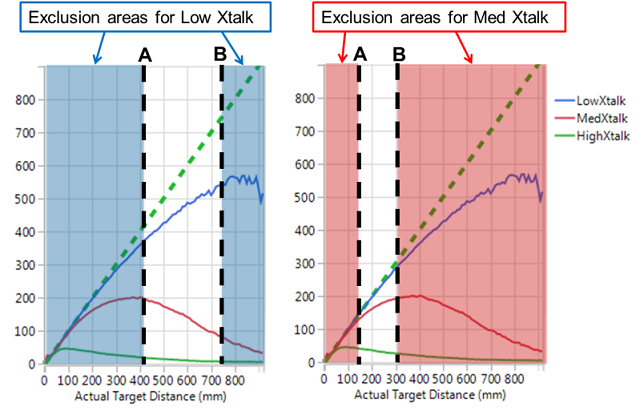
- Cross-talk calibration - Calibrates the "cross-talk" that is received from a close reflected surface such as a glass cover on the sensor. This must be performed if using a clear cover on the sensor or an aperture that restricts the viewing angle of the sensor. More information about calibration with a glass cover is detailed in this application note.
Each of the MappyDot Plus offset and cross-talk calibration modes require the measurement settings to be set appropriate to the calibration target distance being measured. The default measurement values of the MappyDot Pluses (47ms measurement budget, short range mode) should be appropriate for most cases.
The target discussed here are standard Munsell neutral chart values (Grey 17% N4.74):
| Munsell | Approximated Colour |
|---|---|
| N4.74 |
Calibration Routine
Reference SPADs Calibration
There are no specific environmental conditions required for calibrating the reference SPADs. If a highly reflective target is covering the VL53L1X module during reference SPAD calibration, the calibration may fail. In this case, user has to move the target away from device.
Offset Calibration
It is recommended to use a white (17% reflectance) target at 140mm, in a dark environment when performing this procedure. Target distance can be changed depending on constraints. You will first need to perform the Reference SPAD routine before calling the offset calibration routine. This routine should be performed after a glass cover is installed if using a glass cover.
Once offset calibration has been completed, be sure to write the current settings as the default startup settings.
Cross-talk Calibration
You will first need to perform the Reference SPAD and offset calibration, before calling the cross-talk calibration routine.
It is recommended to use a grey (17% reflectance) target in a dark environment when performing this procedure. Next choose the distance required for this target depending on the type of cover being used:

Once cross-talk calibration has been completed, be sure to write the current settings as the default startup settings.
Registers
The MappyDot Plus can perform the above VL53L1X API calibration routines using the following configuration registers:
- a (0x61) [target_distance_bytes] - Calibrate Distance Offset
- x (0x78) [target_distance_bytes] - Calibrate Crosstalk
- u (0x75) - Calibrate Reference SPAD
If these routines fail, the LED will blink a calibration fail code.
Code Example
Here's an Arduino code sample for performing the offset calibration routine:
#define CALIBRATE_DISTANCE_OFFSET                   (0x61)
#define CALIBRATE_SPAD                              (0x75)


void mm_to_bytes(uint8_t *bytes, uint16_t mm)
{
    bytes[0] = (mm >> 8 & 0xFF);
    bytes[1] = (mm & 0xFF);
}

void offset_calibration_routine()
{
  set_led_mode_off();

  delay(200);

  /* Calibrate SPADs */
  Wire.beginTransmission(address);
  Wire.write(CALIBRATE_SPAD);
  Wire.endTransmission();

  delay(1000);

  /* Calibrate Offset */

  uint8_t calib_dist = 100; //In millimeters
  uint8_t dist_bytes[2];
  mm_to_bytes(dist_bytes, calib_dist);
  Wire.beginTransmission(address);
  Wire.write(CALIBRATE_DISTANCE_OFFSET);
  Wire.write(dist_bytes[0]);
  Wire.write(dist_bytes[1]);
  Wire.endTransmission();

  delay(10000);

  Serial.println("Calibration Complete");
}