SensorDots Development Board
The SensorDots development board is a handy breakout board for use with the range of SensorDot modules.
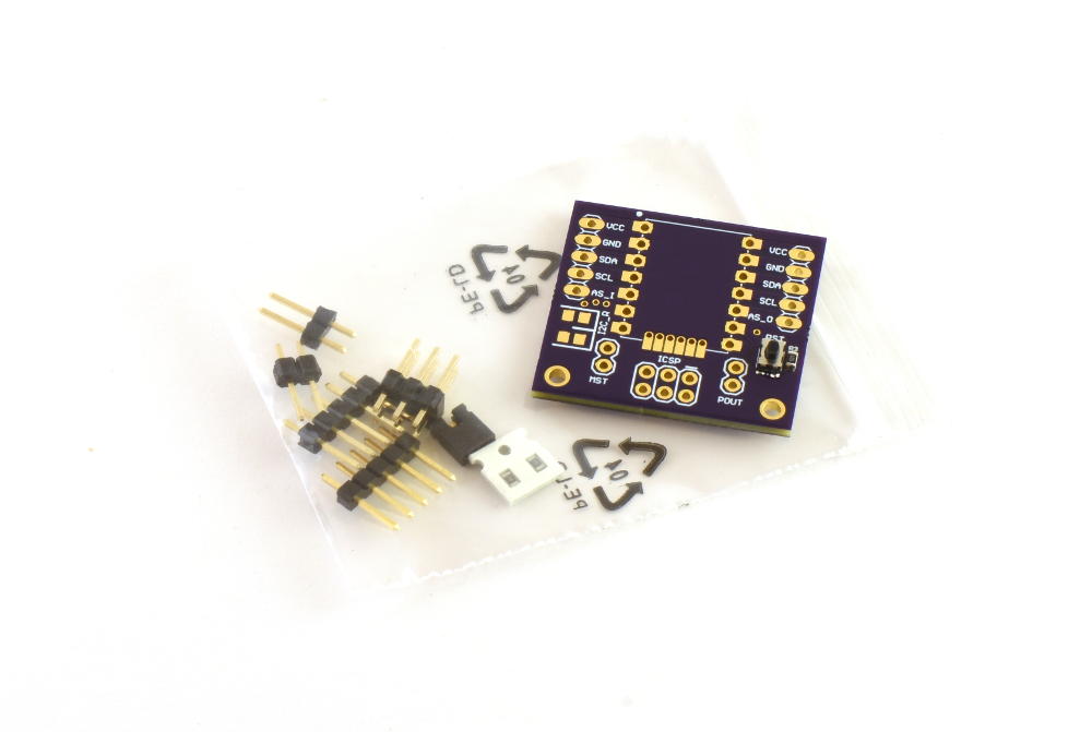
The SensorDots development board gives you the option to either connect 2.54mm (0.1") headers to the SensorDot boards for easy removal, or to solder the SensorDots directly to the board. It brings out the ICSP programming headers and has a reset button, master select jumper, optional I2C resistors and mounting holes for development use. Note these resistors are optional as there should only be one set of resistors on an I2C bus and this will depend on your specific setup.
Soldering the optional (if you want to use the ICSP connection to program the board instead of the I2C bootloader) 1.27mm bottom header holes can be achieved by first aligning and soldering the SensorDot board to the Dev board using the main castellated (cut out) side pins. Once you have done this you can now tin the 6 bottom ICSP pads on the Dev board with some solder (not the 2.54mm header pads, but the 6x1.27mm pads in a row), then hold the iron on one tinned pad and feed solder through the top of the corresponding 1.27mm pitch hole on the SensorDot board and wait for the solder to start flowing into the hole. Once it starts flowing a connection should now be made and you can remove the solder wire (you don't need too much solder). Now repeat this process for the remaining 5 pins. Be sure to check for any shorts with a multimeter once soldered and remove any excess with a solder wick.
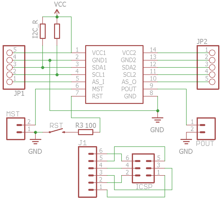
The development board schematic and production files are located on the GitHub repository. You can order the PCB here on OSHPark. They are also available for sale with the SensorDots as a kit with headers.