I2C Interface Specifications
As the SensorDots use the ATmega328PB, they share the same I2C client device characteristics.
The interface has:
- Up to 400kHz Data Transfer Speed
- Slew-rate Limited Output Drivers
- Noise Suppression Circuitry Rejects Spikes on Bus Lines
Both I2C bus lines are to be connected to the positive supply VCC voltage through pull-up resistors. The bus drivers of all devices are open-drain or open-collector. This implements a wired-AND function which is essential to the operation of the interface. A low level on an I2C bus line is generated when one or more I2C devices output a zero. A high level is output when all I2C devices tri-state their outputs, allowing the pull-up resistors to pull the line high. Note that all MappyDot devices connected to the I2C bus must be powered in order to allow any bus operation. The number of devices that can be connected to the bus is only limited by the bus capacitance limit of 400pF.
Interface Characteristics
These tables have been taken from the ATmega328PB datasheet.
The following table describes the requirements for devices connected to the I2C Bus. The I2C Interface meets or exceeds these requirements under the noted conditions.
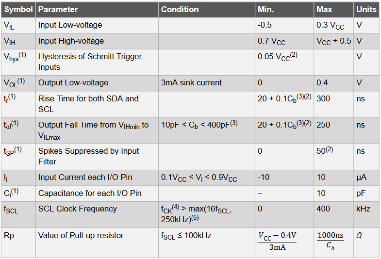
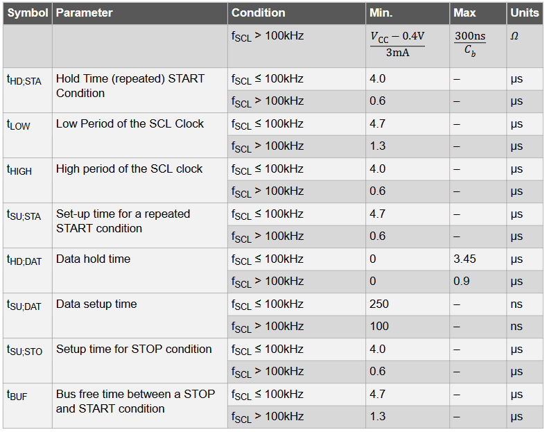
Note:
- This parameter is characterized and not 100% tested.
- Required only for fSCL > 100kHz.
- Cb = capacitance of one bus line in pF.
- fCK = CPU clock frequency which is 8MHz
- This requirement applies to all 2-wire Serial Interface operation. Other devices connected to the I2C Bus need only obey the general fSCL requirement.
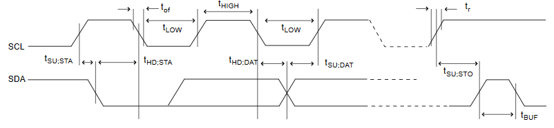
Timing symbols refer to the following timing figure:
More information about the I2C interface is available on page 250 of the ATmega328PB datasheet.