Firmware Update Guide
The SensorDot boards can be easily programmed over I2C using the Multiboot Tool in the GitHub repository under Windows or Linux. This tool will reboot the selected SensorDot board into its firmware flashing bootloader which then allows you to re-program new firmware.
Hardware Setup
USB Adapter
Windows and Linux x86 platforms generally don't have easily accessible I2C peripherals, so to account for this, an Arduino/Teensy based USB to I2C adapter has been created to allow you to program SensorDots easily which works with a modified version of the Multiboot Tool (twiboot-arduino). This adapter is available in the repository here.
This adapter has been tested using the Teensy 3.1/3.2/3.5/3.6/LC, Arudino Nano and Arduino Uno. While every effort has been made to make it compatible with most Arduino boards, there might be compatibility issues with devices not listed here (especially if you are using a clone board). Please feel free to contact us if you are having issues with other boards. As a troubleshooting step, make sure that the board works with the generic I2C scanner demo. Please note that we won't support clone boards as they can have numerous issues, however it generally should work with these if other I2C sketches work, with some slight driver tweaks (see Tips section down the bottom).
Load this sketch onto your Arduino board of choice using the Arduino IDE. For more information about programming Arduino sketches, please refer to the Arduino getting started guide.
If you are using an Arudino based device, you might need to connect a 10μF capacitor between the Reset/RST line and GND if the Arduino based board uses a DTR line to reset the Arduino for programming. This might depend on which operating system you are using (as you can disable DTR with stty in Linux), but it's the most reliable way of programming your SensorDot boards. There's more information here - https://playground.arduino.cc/Main/DisablingAutoResetOnSerialConnection. Teensy boards do not require this. Note you will need to remove the capacitor if you are wanting to program the Arduino again.
UPDATE, there is now a -z flag in the twi-arduino executable that can be given which delays the I2C commands after opening the port, so you don't need to place a capacitor on the reset lines.
Embedded Platforms
As for embedded systems running Linux such as the Raspberry Pi with a built in I2C peripheral, you can directly use the /dev/i2cX device drivers built into most operating systems. You may need to enable I2C on these devices before they show up. On the Raspberry Pi, you can enable I2C with the following steps:
- Run
sudo raspi-config. - Use the down arrow to select
Advanced Options - Arrow down to
I2C. - Select
yeswhen it asks you to enable I2C - Also select
yeswhen it tasks about automatically loading the kernel module. - Use the right arrow to select the
<Finish>button. - Select
yeswhen it asks to reboot.
Now that the the I2C peripheral or adapter is ready, you can now connect the I2C lines to the SensorDots I2C lines as per the getting started guide. Note, if you are already using an Arduino device to talk to your SensorDots boards, you can load the sketch onto this over the existing sketch. You can also load the adapter separately on the I2C bus as a second master device (just be sure to stop communications from other master on the bus).
Windows
Under Windows, you must use the Arduino based USB to I2C adapter, as Windows doesn't include I2C drivers that are compatible with the Multiboot Tool.
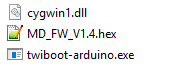
The Multiboot sources must be compiled under Cygwin by running "make" in the source directory while in the Cygwin shell. There is a pre-built executable available if you prefer not to perform this step (just download the cygwin1.dll and twiboot-arduino.exe files from GitHub and place in a directory of your choice).
Once you have the executable ready, place the correct SensorDot board firmware in the same directory as the exe (e.g. MD_FW_V1.4.hex). These firmware files are available in the Releases folder of the firmware of choice in the repository.
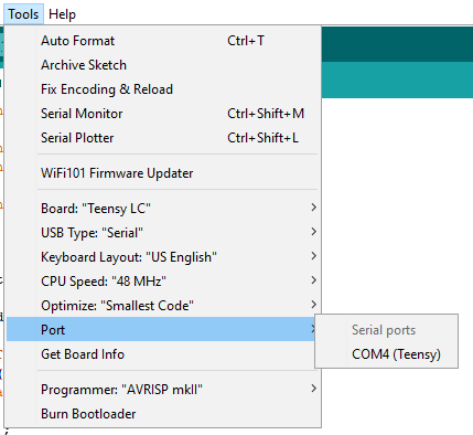
Next find the COM port number of the Arduino adapter. In Arduino this can be found by going to Tools>Port:
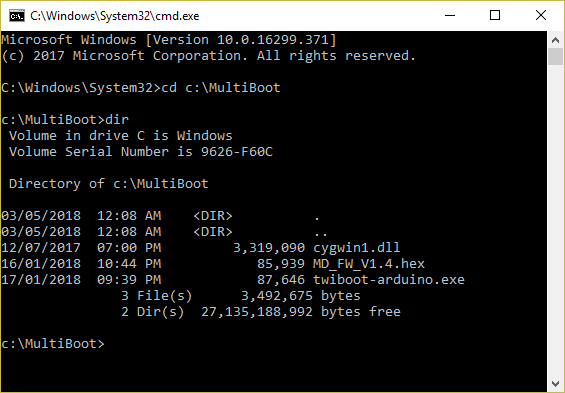
Browse to the twiboot-adruino.exe directory using the command prompt (Start>Run>cmd):
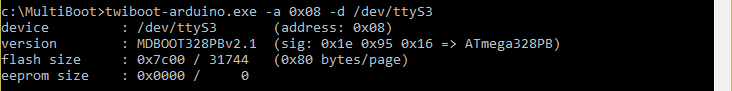
Now run the following command for COM4 to test everything is working, where the tty serial device number is the Windows COM number, minus 1 (e.g. for for COM5 it's /dev/ttyS4). The -a flag indicates the SensorDot I2C address (0x08 is the first in the chain).
twiboot-arduino.exe -a 0x08 -d /dev/ttyS3
If you get the error "error 22 from tcgetattr", open the COM port in a terminal application like Putty first (then close Putty), then run the command again.
You should get the following (and the SensorDot board LED should be rapidly flashing which indicates it is in bootloader mode):
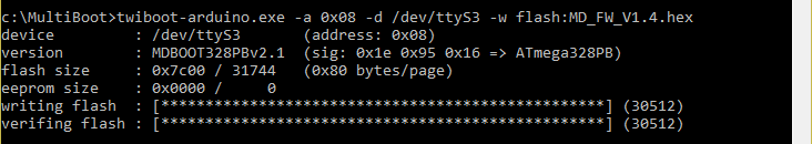
Now you can run the firmware update routine:
twiboot-arduino.exe -a 0x08 -d /dev/ttyS3 -w flash:MD_FW_V1.4.hex
Once the firmware had flashed successfully, you can now reboot the SensorDot using the following command:
twiboot-arduino.exe -a 0x08 -d /dev/ttyS3 -s
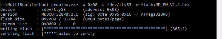
If you get a failure, please retry the firmware update routine:
Linux
The Multiboot sources must be compiled under Linux by running "make" in the source directory.
Once you have the executable ready, place the correct SensorDot board firmware in the same directory as the executable (e.g. MD_FW_V1.5.hex). These firmware files are available in the Releases folder of the firmware of choice in the repository. Note there are two versions of the application here, twiboot and twiboot-arduino. The twiboot application is used when you have an embedded I2C peripheral on board and the twiboot-arduino version is used when you want to use the Arduino based USB to I2C adapter.
Embedded Platforms
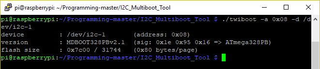
Now there are two options to flashing the firmware under Linux. The first is if you are using an embedded system with I2C hardware. In this instance you simply run the following (where /dev/i2c-1 corresponds to your I2C device to make sure everything is working:
./twiboot -a 0x08 -d /dev/i2c-1
You should get the following (and the SensorDot board LED should be rapidly flashing which indicates it is in bootloader mode):
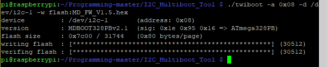
Now you can run the firmware update routine:
./twiboot -a 0x08 -d /dev/i2c-1 -w flash:MD_FW_V1.5.hex
Once the firmware had flashed successfully, you can now reboot the SensorDot using the following command:
./twiboot -a 0x08 -d /dev/i2c-1 -s
USB Adapter
The second option is to use the Arduino based USB to I2C adapter. First find the serial port device associated with the adapter using dmesg | grep tty:
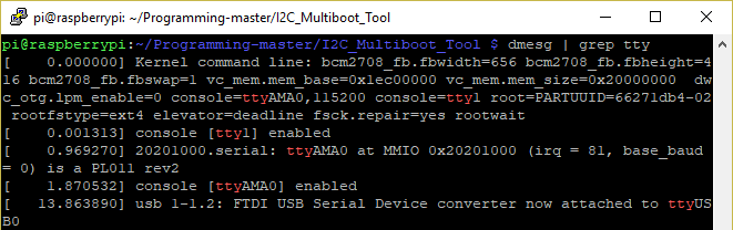
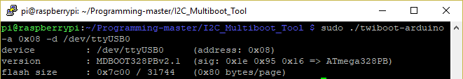
In this instance, the device is /dev/ttyUSB0. Now run the following to make sure everything is working:
sudo ./twiboot-arduino -a 0x08 -d /dev/ttyUSB0
Now you can run the firmware update routine:
./twiboot-arduino -a 0x08 -d /dev/ttyUSB0 -w flash:MD_FW_V1.5.hex
Once the firmware had flashed successfully, you can now reboot the SensorDot using the following command:
./twiboot-arduino -a 0x08 -d /dev/ttyUSB0 -s
Tips and Recovery
If you have more than one SensorDot board, you can now increment the I2C address in the command and program the next board in the chain. You must reset the previous SensorDot board before programming the next one in the chain.
It is recommended that you make sure each SensorDot board is successfully verified and boots correctly before moving onto the next device. If you batch script the programming and multiple boards fail to program correctly, or a power supply glitch restarts boards during programming, you may find a situation where you cannot get boards to enter the bootloader and some boards will no longer get their auto addressing.
There are a few options in this case, depending on the condition of the boards.
The first is applicable if one device has had an incorrect or badly modified firmware flashed and it still boots correctly, but it stops the rest of the devices in the chain from getting an address and it doesn't respond to commands itself. In this instance, just restart the affected board by pulling/shorting the RST pin to ground on that board before power up. Once pulled to ground, remove the short and run the twiboot(-arduino) -a 0x07 -d /dev/ttyS3 command within 500ms, and the device should stay in bootloader mode (continuous rapid flashing). You can then perform the firmware update procedure once again.
In the instance where one or multiple boards are stuck in bootloader mode after a failed flashing and/or power glitch (continuous rapid flashing), you will need to hold the RST line on all affected SensorDot boards on the bus to ground before power up. Once pulled to ground, remove the short on one device and run the twiboot(-arduino) -a 0x07 -d /dev/ttyS3 command within 500ms, and that device should stay in bootloader mode (continuous rapid flashing). You can then perform the firmware update procedure once again then reset the board (twiboot-arduino.exe -a 0x07 -d /dev/ttyS3 -s). Now run this for each of the other affected boards one by one.
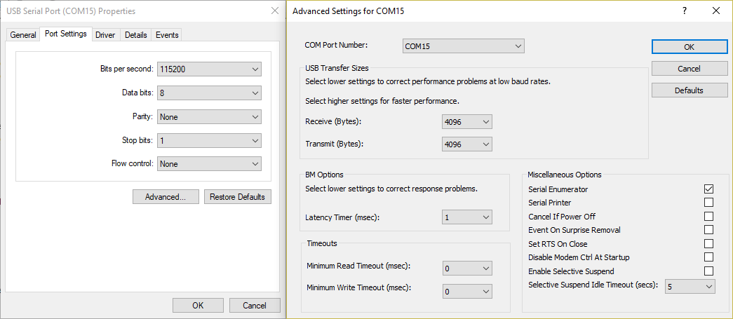
If you get the error failed to get chipinfo: No error and you are using an Arudino clone using a fake FTDI chipset, you might have to set the Latency Timer to 1 in device manager under Windows. The baud rate should also be set to 115200. This is also useful if your device fails to verify on certain PCs.